Advertise on fullfatrr.com »

Home > In Car Electronics (L322) > LCD instrument cluster repair
Post Reply  Down to end
Page 2 of 2 <12
Print this entire topic · 
doclees


Member Since: 25 Jun 2015
Location: PA
Posts: 672

United States 2004 Range Rover HSE 4.4 V8 Java Black

Thanks Mistercorn, that's what I want to hear. Mine is getting bad. Must be the heat. Got to do it soon. Was yours through Akspeedo and did you need to drill?

Post #338840 24th Jul 2015 2:04pm
View user's profile Send private message View poster's gallery Reply with quote
Mistercorn


Member Since: 01 Feb 2014
Location: Nottingham
Posts: 109

United Kingdom 2010 Range Rover Autobiography 4.4 V8 Java Black

I have just checked on my eBay history, it was through Akspeedo, May 2013. I vaguely remember something about doing some drilling, but you are asking me to remember what I spent a short time doing over two years ago. As my Dad would say, I've been to bed since then... What I do remember is that getting the wood trim pieces at the end of the dashboard off was about the most awkward part of the job.

MC

Post #338849 24th Jul 2015 2:16pm
View user's profile Send private message View poster's gallery Reply with quote
jakebullet64


Member Since: 28 May 2014
Location: Wolverhampton
Posts: 259

United Kingdom 2003 Range Rover Vogue 4.4 V8 Santorini Black

Well mine was back from cartronix yesterday and fitted this am, it's great.
Sent it Wednesday, they received it Thursday and repaired and returned it same day. Can't fault them for service.
I Struggled a bit getting the wood trim back on.
Jake 2003 Range Rover Vogue 4.4 on Gas
1961 88" 2.25 diesel - George
Gone - 1997 3.9 V8i Discovery - Burt

Post #339085 25th Jul 2015 9:48pm
View user's profile Send private message View poster's gallery Reply with quote
doclees


Member Since: 25 Jun 2015
Location: PA
Posts: 672

United States 2004 Range Rover HSE 4.4 V8 Java Black

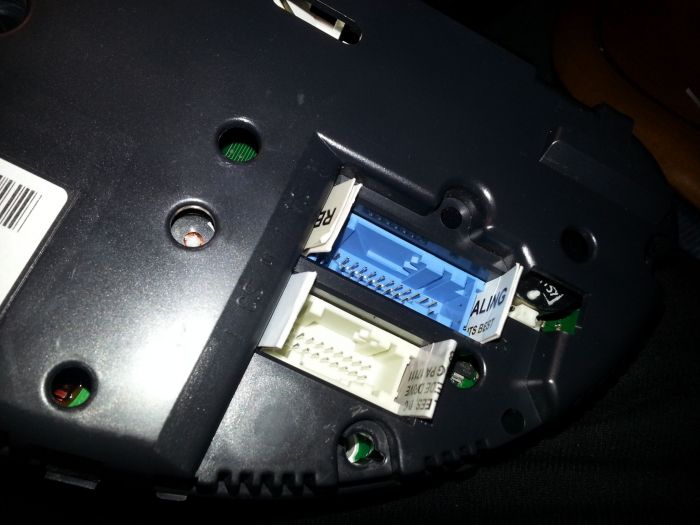
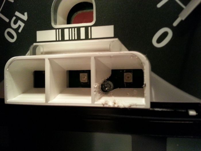
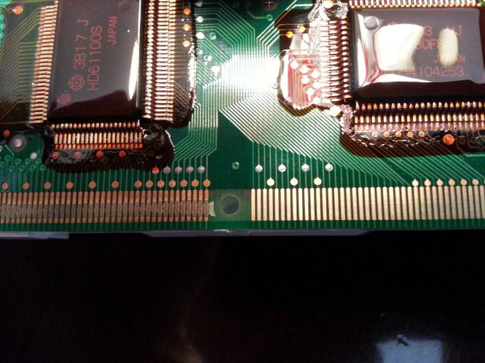
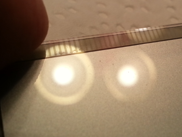
In doing more internet research I've got a fairly clear idea of the problem and the fix. To answer my own question as to cleaning and reseating the cable it has been done. The old cable tends to lose some of its conducting material to the old glue. This necessities one to position the old cable a bit higher. Doesn't seem to be worth it. I'll get a new cable. The second problem is with the silicon pieces on the LCD bar. They compress and age over time making them thinner. Their thickness. Is needed to help make proper ribbon cable contact. Paper spacers have been used behind the silicon to restore the needed contact pressure. The last issue of concern is the drill method to get to the retaining screws without removing the gauge needles. If they are in identical or near identical position as on the x5 I don't see an issue. As I see it you are drilling through the plastic face with no circuit board parts. Just set a stop on your drill bit so you can't drill past the thickness of the plastic face. No worries to the circuit board below. Am I missing something?

Post #339275 27th Jul 2015 12:21am
View user's profile Send private message View poster's gallery Reply with quote
doclees


Member Since: 25 Jun 2015
Location: PA
Posts: 672

United States 2004 Range Rover HSE 4.4 V8 Java Black

Just an update. Got my ribbon cable from akspeedo. About 1 week from UK to PA USA. It includes a drill template and pass codes for instructions. I'll take pics of the procedure. May take a week for me to get to it.

Post #340684 4th Aug 2015 12:20am
View user's profile Send private message View poster's gallery Reply with quote
Welshdragon


Member Since: 20 Jan 2012
Location: here and there...but not where I should be
Posts: 1898

Wales 2003 Range Rover Vogue 4.4 V8 Monte Carlo Blue

Thumbs Up
Good luck, it was one job I was not happy to do myself. If it dont work.......burn it!

If the IId tool cant fix it.......burn the FF.

If the FF cant be fixed......buy a Land Cruiser!

If the LC cant be fixed..............................................BUY a horse !!

Post #340692 4th Aug 2015 7:42am
View user's profile Send private message View poster's gallery Reply with quote
wayneg


Member Since: 05 Jun 2013
Location: South Fremantle, Australia ( ex London )
Posts: 775

Australia 2007 Range Rover Vogue SE TDV8 Java Black

I have recently replaced the ribbon cable with one from AKSPEEDO. With the cable comes links to website instructions with passwords to access, also paper templates to drill holes to expose screws. This saves removing the dial needles which can do damage. I chose to drill the holes as you peel back the clock faces a little, drill the holes then once replaced the faces cover the holes. The process although time consuming was relativly pain free with a perfect result. I would not have tried with the heat bonded types. 100% perfect readout when finised.
I would suggest using a Dremmel type drill to make the holes 2007 TDV8 VSE
2003 TD6 gone.
2002 P38a gone
1999 P38a gone
1997 p38a gone
1993 VSE gone
1992 VSE gone
1966 Series 2a with V8 conversion gone

Post #342711 16th Aug 2015 5:08am
View user's profile Send private message View poster's gallery Reply with quote
doclees


Member Since: 25 Jun 2015
Location: PA
Posts: 672

United States 2004 Range Rover HSE 4.4 V8 Java Black

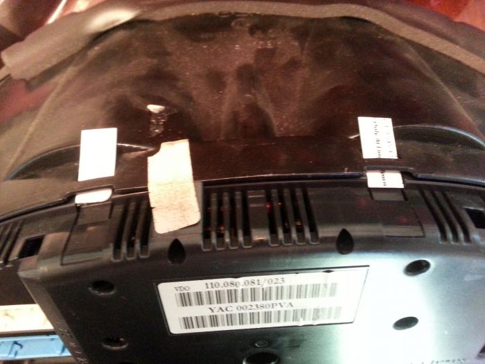
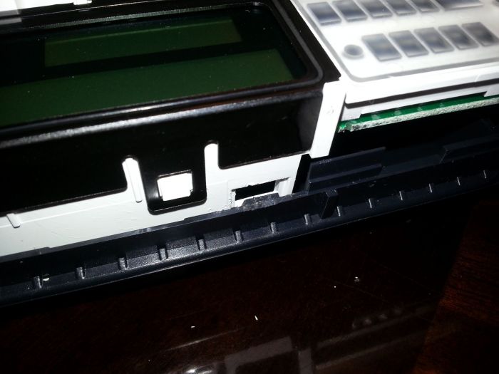
Just finished the ribbon cable replacement. I will post some pictures later but I have some pointers.
**** I didnt disconnect battery at first. After pulling cluster random lights would come on and stay on. ****

1. Instructions are lacking. They show replacement on a cluster with the needles removed. YouTube videos do the same. They state there are 8 large torx screws holding the dash down. I only found 7. In removing the vent the instructions say push the tabs in. I took that to be push them flat with the vent wall. No just the opposite.
1a. The X plastic tabs helping to hold the cluster case together are just plastic you bend. They seem to be more important for alignment of the case halves and not needed for securing the halves. If they break don't worry. The catch tabs are the important ones. I found using business card stock folded in 4 tucked under the rim makes it easy to separate the halves. Pictured is my first attempt. It worked but with more effort.


1b. The electrical connectors on the board snap into the rear case half. Doubled up card stock holds the tabs out of the way so you can focus on the other catch tabs.


2. The template is more of a guide map than a template you can place over and drill. But you can hit the mark and you dont need to be spot on for it to work.
3. There is plenty of space between the plastic and the board so if you drill with even moderate caution you won't hit the board.
4. The dial face is a flexible plastic but thick. It makes you nervous bending it out of the way but it bends enough.
5. Use a sharp drill bit. You can go nice and slow.
6. Under the dial faces there is ribbed clear plastic that distributes light. The plastic is stiff, doesn't drill well and cracks easy. After the first one I used a soldering iron with a blade tip to melt/cut this first and just drill the white ABS/PVC under it.
7. I have no idea how to safely drill out the plastic over the screw second from the right. Again I used my soldering iron. I had a spade shaped blade at an angle that would have made it a 30 second job but the threads were stripped so back to the blade tip.


8. Cleaning the board contacts with acetone takes a bit more scrubbing than I expected.


When removing the metal frame that hold the LCD screen press the metal frame towards the plastic catch before lifting the 3 tabs to prevent them from shaving some of the plastic catch. A shaved catch is hard to catch again. Doable but hard.


9. The downloaded instructions say to use glossy photo paper behind the rubber pressure pads. The instructions sent say to use the enclosed cardboard the ribbon is attached to for shipping. Probably doesn't make a difference. I noticed the large rubber pad had indent marks from the old ribbon cable. I flipped it over so a non indented side would contact the ribbon.
10. When aligning the ribbon to the board it says use tape to hold in place. At first I used a wide piece but that may cause uneven pressure. If you tape the whole cable its near impossible to align it. I used a very small piece at each end and a very small piece in the center. It aligns easy but be sure it is even across the top and flat.
11. When pressing the LCD bulb holder back on the board the the large rubber pad may fall out. Don't worry you can put it in from the front. One of my screws stayed in place. If you have that be sure it is aligned with the threaded hole. Installation of the screws will pull the bulb holder close to the board but still may need some end squeezing.
12. If you got the ribbon aligned to the board well, alignment with the LCD is automatic. Look at the LCD contacts in the light. You will see a separation in the pattern. I used a very thin piece of green tape here to help align with the visible contacts on the ribbon but it will align if the board alignment is good. If you see any bunching or air pockets upon pressing the LCD to the ribbon the alignment is off at the board.
12a. Im not sure what the imperfections in the LCD contacts means whether it is normal or an indication the LCD is getting old. *** just been told by AKspeedo that this indicates the LCD is going bad. That said my display look good now. Even if I do need to change the LCD later the hard work has been done. I can pop the metal cover off and replace the LCD without removing from board. *****


13. When mounting the LCD frame over the LCD be sure the tabs lock in place. The white plastic sticks through the metal tabs so when squeezing be sure you are on both edges of the metal tab.
14. I will edit more later.

I was asked how long did it take. Actually doing something time would be about 3 hours. Maybe 6 hours of being with it time trying to not make a wrong move. Now that I know what to do I think I could do it again in under 2 hours.

Post #345077 30th Aug 2015 2:45am
View user's profile Send private message View poster's gallery Post Reply
Post Reply  Back to top
Page 2 of 2 <12
All times are GMT + 1 Hour

Jump to  
Previous Topic | Next Topic >
Posting Rules
You cannot post new topics in this forum
You cannot reply to topics in this forum
You cannot edit your posts in this forum
You cannot delete your posts in this forum
You cannot vote in polls in this forum


Site Copyright © 2006-2024 Futuranet Ltd & Martin Lewis
fullfatrr.com RSS Feed - All Forums


Switch to Mobile site