Ajmngn
Member Since: 25 May 2021
Location: Cambridgeshire
Posts: 210

 
|
| How-to - Starter Relay Mod | |
Why should you consider this mod?
In short, reliability of your starting system. Weak and/or low batteries are a known issue in the 2010-12 models due to the number of ECUs, and this can contribute to starting issues. Starter motors and contact wear is another known issue that has caused many to replace their starter motor, possibly unnecessarily. Whilst this modification does add additional complexity (through another electrical circuit and components that may fail), this is a small price to pay for the single most robust method to send maximum power down to the starter motor solenoid. What you get in return is a mod that can overcome weak batteries in some scenarios, and worn (but not broken) starter motor solenoids. Both of these issues are then also much easier to diagnose when you have a genuine issue.
What will you need?
Essential Items
- A 12V 4 pin high power relay. ***Warning – ensure it is a normally open relay and not normally closed relay; others have made this mistake***. These are about £10-15 from any reasonable supplier (eBay, Amazon, RS Electronics etc). I suggest you buy two and keep the second in the car to overcome the ‘what if my additional relay fails’ argument.
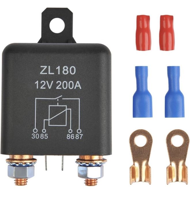 | | Click image to enlarge |
- In line midi fuse and holder. I went for 80A based on my chosen cable size, ensuring the fuse will blow well before the cable melts.
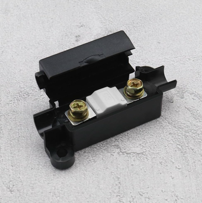 | | Click image to enlarge |
- Thicker Gauge Wire for Battery to Starter Solenoid Line. I went for 16mm2 (5AWG), which is rated for 110A. You could downsize if you wished as mine went overkill, but I had some logic (see below).
- Thinner Gauge Wire for Control Line. I went for 6mm2 (10AWG), which is rated for 55A. This is also excessive but based upon the 40A inline fuse in the existing car starting circuit.
Desirable/Optional Items
- Copper ring lug terminals
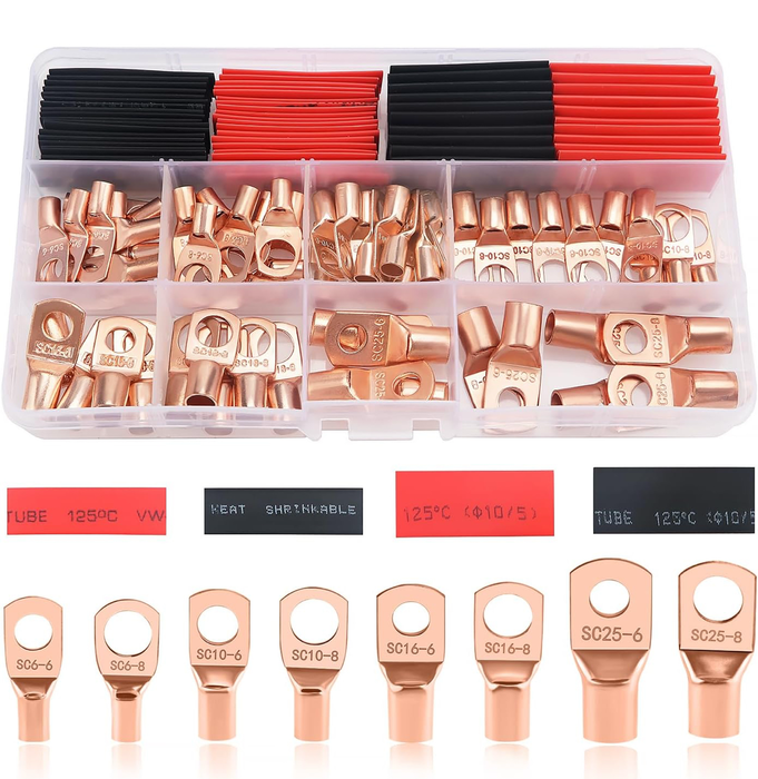 | | Click image to enlarge |
- Rubber grommets
- Shrink wrap tubing
- Terminal pin connector for wiring loom
Tools
- Spanners/socket set
- Drill and bits to suit cable size
- Cable cutters and crimping tools
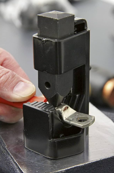 | | Click image to enlarge |
Explanation of the Mod
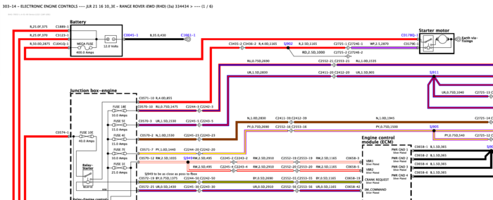
The current starter system can be seen on this section of the workshop manual (Electrical Diagrams/Electronic Engine Control)
For those not familiar with a standard starter motor, it is essentially two parts: a solenoid (switch) and a powerful motor. When you turn the ignition key or push the start button, this closes a circuit that provides power to the solenoid mounted on the starter motor. This solenoid then completes a second much higher capacity circuit that provides power from the battery directly to the starter motor. In the 2010-12 FFRR this circuit is rated to 400A and uses a very thick cable capable of the power demand. This is why you need a 90Ah 850 cold-cranking amp (CCA) battery. Anyway, once the high-capacity circuit is made, it’s simply a case of having enough CCAs to turn the engine, as it is a very big lump to get moving. Low battery can mean no start as not enough power to turn the engine with the starter motor. The starter motor itself can fail, but it’s a pretty simple bit of kit, it’s designed for thousands of starts, and it’s the same system on pretty much every combustion vehicle so a well-proven technology. The solenoid on the other hand is nothing more than a simple micro-switch. It needs power to energise a coil which creates a magnetic field and this mechanically pulls a contact closed. The mechanical part of the solenoid can get stuck, and if the magnet created is not powerful enough then this can prevent the solenoid from operating. It is also a relatively delicate item so can be more susceptible to failure. It is this specific part of the system that we are trying to optimise.
In the 2010-12 FFRR, this solenoid is controlled by an ECU. The ECU sends 12V down a cable that is over 4.5m long and goes through at least two connectors on the journey. The cable also goes from a 4mm2 cable in the first section down to a 2.5mm2 cable in the last 2.9m before reaching the starter solenoid. This cable is a significant weak point due to resistance. The resistance in copper wire is directly proportional to its length - if you double the length you double the resistance. The cable is also routed around the engine bay which is not ideal as resistance along a wire increases with temperature. In addition to this, connection points will always be susceptible to corrosion which is another potential factor that would increase resistance. Therefore, this single cable has significant potential to fail to meet the electrical demands of the starter solenoid if the resistance cannot be overcome. This will manifest in a no-start if it cannot provide sufficient power to close the solenoid switch which connects the battery to the starter motor.
What we are doing in this mod is using the wire between the ECU and the starter solenoid to power a new relay instead of the starter solenoid. This is a much lighter demand on the circuit and one that is unlikely to ever fail as long as the relay is working. When the relay is operated (closed) this creates a circuit directly between the vehicle battery and the starter solenoid. The logic is that using this method, the starter solenoid is able to access as much power as it needs to close, thus giving it the power to operate in all but the most extreme conditions. Furthermore, if this method of powering the starter solenoid fails it means that the solenoid is broken and needs to be either rebuilt or replaced so helps diagnose starting issues. As a slight aside, I contend that a significant proportion of those 2010-12 FFRR owners changing out starter motors don’t actually have a broken starter. I believe what’s happening is that the solenoid is demanding more power than the standard circuit can provide as resistance is too high, but this is incorrectly diagnosed as a faulty starter.
So how do I do this mod?
In simple terms there is an easy, but arguably less optimal, method as it requires cutting into your existing vehicle wiring loom. I chose a harder but more robust method as I made up a new wire with a terminal pin, which meant I was not cutting into my loom and could restore the vehicle to standard very easily. The easy and the hard method are otherwise the same for three of the four main parts.
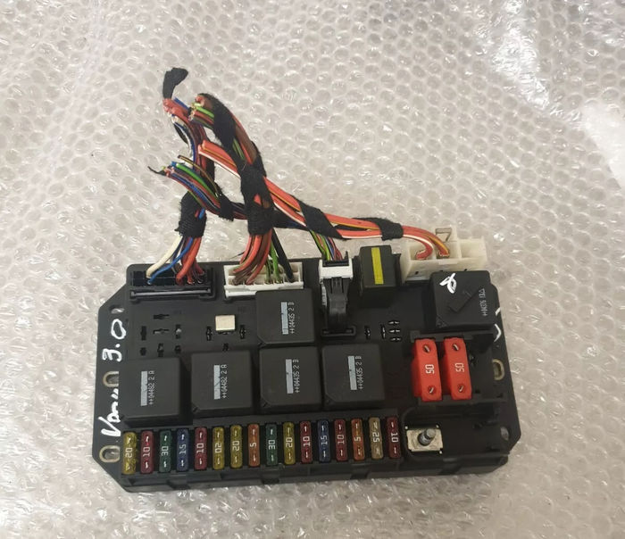
Prelims – Identify a mounting point for your new relay.
I chose the bulkhead as there was an unused threaded stud that was out the way and ideally located (picture below). It was also close to the Junction Box-Engine and earth points. Others have mounted theirs closer to the starter motor or on the side of the engine bay in the vicinity of the air filter housing. Whichever location you chose, do this first as this will determine how long your cables need to be between the new relay and the various connection points.
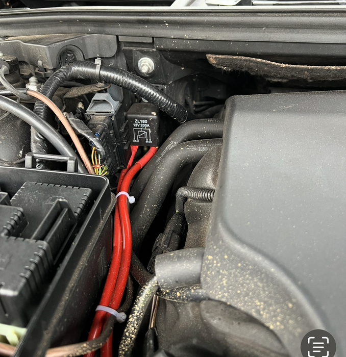 | | Click image to enlarge |
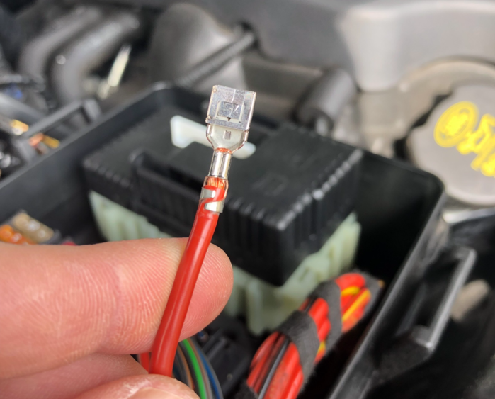
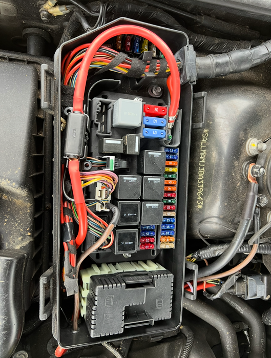
Step One – The hard method. Starter circuit trigger to Relay Pin 86.
You need to identify the cable in the junction box-engine that provides power from the car’s integral starter relay (switch) to the starter solenoid (the 4.5m long one). This can be found in pin 10 of the white plug (pic below). The hard method involves removing this wire and pin from the plug, and replacing it with a new much thicker wire (I used 6mm2 10AWG). The way I did this, which I believe is the gold-plated solution, was to source a new terminal pin and crimp that onto my new wire, so replacing the original wire in the plug with a new one. I then drilled a hole in the side of the plastic box, placed a rubber grommet in the hole, and routed the cable into the engine bay to the new relay and pin 86. I did not add an in-line fuse as there is already a 40A fuse in this circuit the other side of the starter relay in the same junction box.
The Easy Method – if you don’t want to go to the trouble of sourcing a terminal pin, you’ll need to cut into the original wire as close to the plug in the junction box as you can. If you are willing to drill a hole in the side of the box then you can do it there and route the cable through a grommet, if you don’t want to do that you will need to trace the loom out the back of the box and unwrap it to find the cable in the loom. *** Caution - I will not advise on this as I don’t know how many red 4mm2 cables are in that loom and how to identify the correct one if you don’t know what you are doing.*** My strong advice is to cut into the cable in the junction box as you can clearly see which is the right cable). The other option is to place your relay down near the starter and use the terminal that was connected to the solenoid and instead connect it to pin 86. I don't think this is a good idea as the relay is low in the engine so exposed to water, plus you still have 4.5m of thin wire down to the relay which is the known weak point. However, this is a way to achieve the same effect without cutting into the loom up in the engine bay and as mentioned above, the demand on the relay is significantly less than the demand from the starter solenoid.
 | | Click image to enlarge |
Step Two – same for both methods. Relay Pin 85 to ground.
You now need to find a suitable ground and connect this to pin 85. I used the same 6mm2 10AWG cable. You have a number of options for your ground point and it just depends on where you choose to mount your new relay. I chose the top of the suspension strut. You could equally make the earth contact on the engine block. What you have just created is the part of the system that will control the opening and closing of the main circuit. In other words, when you turn on the ignition, it will power the relay and close it to create a circuit between pins 30 and 87 which are the higher capacity part of the relay.
Step three – Battery to Pin 30.
I used 16mm2 5AWG cable for this along with an in-line 80A midi fuse and holder. You need to mount the fuse close to the battery end of the wire, not close to the relay. You have a number of options on where to connect to the battery, the first being the battery itself. This just requires a longer run of cable and routing it down the back of the engine (which gets very hot) so needs to be done with care. I chose to connect to the main power supply in the junction box-engine – the big fat red cable that provides power to all the circuits in the engine bay. Just like the trigger wire, this required a hole to be drilled in the side of the junction box and adding a grommet. However, making the connection is much simpler as it’s just a ring terminal and a bolt. Plus, it’s a weather-proof location to have the fuse.
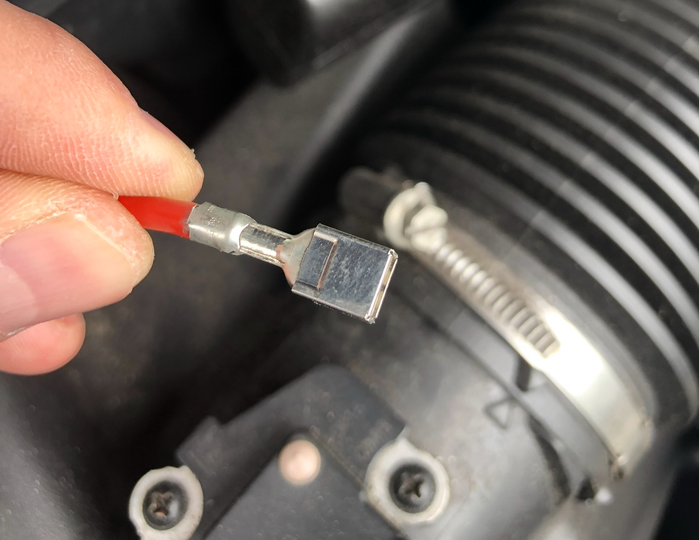
Step four – Pin 87 to starter solenoid.
I used 16mm2 5AWG again and routed the cable down the side of the engine bay between the air filter housing and side panels, down the front behind the lights, and then into the location of the starter motor. There are two wires on the starter motor and you cannot mix them up. One is red and very thick – leave this alone as this is the cable to the battery. The other is 2.5mm2 and white/purple on a small stud connector. This is the connection you want. If, like me, you went into this line at the plug in the junction box, this is essentially a dead cable so I removed it from the terminal and just taped it to my new one out of the way. If you have cut into this cable ‘upstream’ then you can leave it in situ so running parallel to the new circuit you have added. There’s no harm in this.
This is basically what you are aiming for:
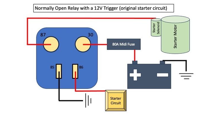
***General warning for routing cables – be extremely wary of where you route new cables in the engine bay. There are moving parts and elements that get very hot, so avoid these areas and ensure that you secure any new cables with ties to be certain it will not foul anything or come into contact with hot parts. The main areas to avoid are down the back and the side of the engine, where the exhaust and turbos are (the hottest parts of the engine). Also be very wary of the fan and pulleys on the front. YOU HAVE BEEN WARNED!!!***
Once done, that’s basically it. If you want to better understand how a starter motor works or how a simple normally open relay works, please do your research. Google, YouTube etc are all your friend and they are very simple and easy to understand parts. I’m happy to answer any basic questions on this process but I’ve covered pretty much everything above. If you are unsure, draw it out on a piece of paper first so you can see the parts and how they work with each other, and familiarise yourself with the components on your vehicle so you know exactly what you are planning to do before you do it. Finally, good luck!! Andy
2010 4.4TDV8 Vogue SE in Santorini Black with Ivory interior
2017 Audi SQ5 3.0 V6T Quattro in Volcano Red
2001 Audi Allroad 2.5 TDI manual with low-range in Highland Green (Currently SORN whilst undergoing some serious restoration!)
Last edited by Ajmngn on 10th Sep 2025 12:03pm. Edited 3 times in total
|