| L322 3.6 TDV8 Steering Rack replacement | |
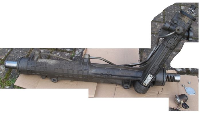
Having identified significant play in the steering rack housing of our 3.6 TDV8 last year (after hoping it was the track rod ends or “drumsticks”), I’d planned to replace the rack this coming summer – when the weather was a bit better for working on the drive.
As usual for the RR, plans went AWOL when the rack developed a big fluid leak from the left hand end (the end that holds the hydraulics on a RHD car) early in January.
The quick summary is that it can be changed on the drive by 1 person & isn’t that bad a job – although it’s not quick. I’ve taken probably 15 hours over 3 days at a very relaxed pace !
Here’s a description for anyone who wants to know what’s involved or the likely man hours required (I’m guessing a garage with motivation should be able to do it in less than 10 man hours).
Its unfortunately long ! I've included some photos as most is fairly self explanatory if you're willing to get this involved in your car. I can supply some if needed.
Symptoms :
Originally, the steering rack housing play was causing minor “play” at the steering wheel when turning either way from straight ahead. There was also a minor “knock” that could be heard & felt.
Weirdly, there was no fluid on the drive due to the leak. The first symptom of the leak was a whining pump & dropping fluid level. All was revealed when I got my wife to operate the steering to full lock each way while I was underneath & there was a massive jet of fluid out of the end of the LH rack boot when the steering got towards full right lock. The internal leak was filling the boot until the boot compressed on right lock, causing it to squirt out. As I don’t use full lock on the drive, it never normally leaked there – lol.
I think the rack seals deteriorated after I restored full PAS pressure after changing the PAS Pump last year (High pressure plus lots of play = unsupported seals & premature failure).
I searched via Google for any “shortcuts” to replace the rack as the Workshop Manual details removing driveshafts, removing the viscous fan etc before dropping the engine subframe. On the internet there was suggestion it could be done without removing the driveshafts, but no detail or confirmation anywhere.
With an unusable car, but good weather & no alternative activities due to the current “lockdown”, I decided to have a go.
( I’d already bought a good s/h steering rack, but no garages with any alleged experience of the job appeared to want the task ! )
What’s involved :
Preparation :
Get a good replacement rack & 3 litres of PAS fluid (Dependant on the replacement rack or parts condition on your car, you may also need rack boots, boot retaining clips, “drumsticks, Track Rod Ends (TREs) & banjo bolt Dowty sealing washers.
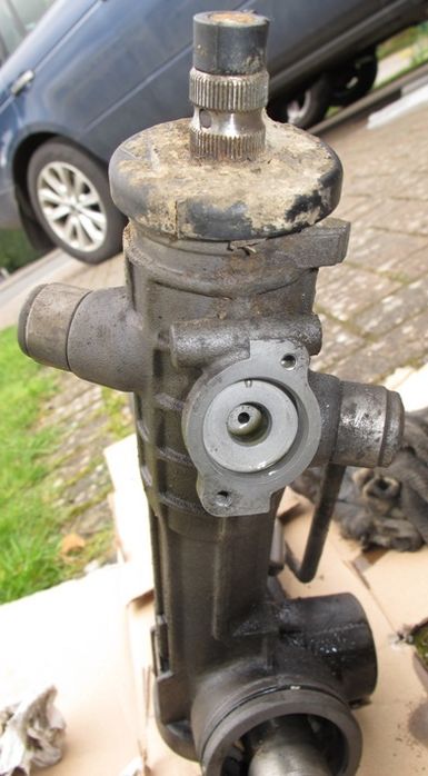
Remove the Servotronic valve from the new rack & make up a plate (eg aluminium or thick cardboard ) to cover the servotronic port on the rack to prevent debris getting in, make the rack assembly smaller & avoid damaging the expensive Servotronic valve during removal & refitting. It’ll need to some short M4 screws to hold it on.
 | | Click image to enlarge |
Remove the TREs if fitted & boots + “drumsticks. Rotate the rack pinion to minimise the exposed part of the RH rack shaft (Leave approx 0.5 inch exposed / don’t allow the rack to go through the seal). Add removable protection to the exposed rack ends (eg a few layers of low tack masking tape).
The Job :
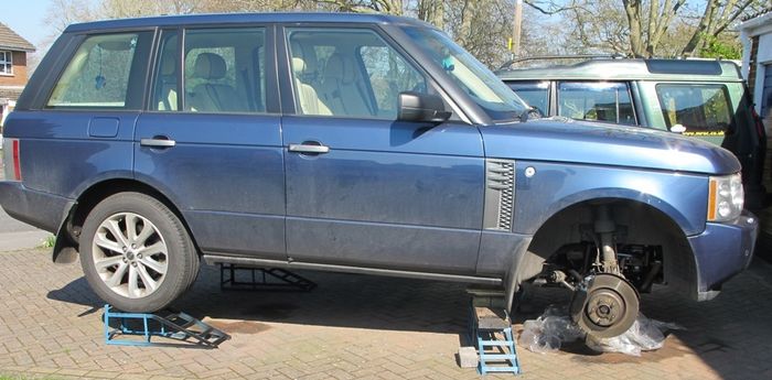
Get the rear of the car onto car ramps, lift the front with a jack & support the body via both LH & RH “chassis rails” just behind the front subframe so that you’ve got space to work underneath safely.
Remove the plastic engine undertrays.
Remove the front road wheels, position the steering wheel to straight ahead, remove the ignition key. Disconnect the battery negative & suck as much fluid out of the PAS reservoir as possible.
Loosen the TRE to drum stick nut if you think you can separate them & separate the TRE from the front hub. Separate the TRE from the drumstick if you can, counting the number of thread turns to remove them (IMPORTANT : This is for use to obtain an approx. correct tracking when re-assembled). Remove the locking nut fully & remove the rack boot retaining clips & boots (gaiters).
If you can’t separate the TRE from the drumstick, expect to replace them with new items as you’ll need them separated to remove the boots & refit to the new rack & adjust the tracking at the end of the job. If they’re seized, but to avoid buying new boots if yours are OK, you can cut the drumstick with a disc cutter or hacksaw.
Once the boots are removed, use a big adjustable spanner to separate the drumsticks from the rack ends. BEWARE : Don’t be too brutal about this as any shock forces you apply will be transmitted to the rack & pinion teeth (more important with your new rack !). It will be fairly tight though !
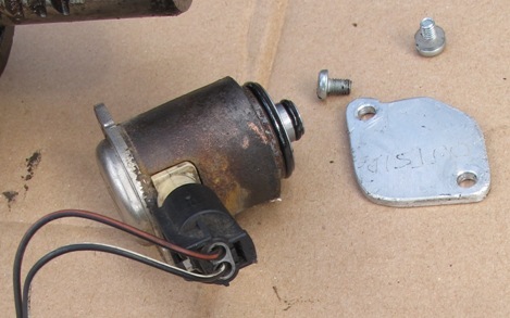
Carefully disconnect the electrical connectors from the servotronic valve & suspension height sensors. Disconnect & remove the height sensors & brackets carefully to avoid damage. Carefully pull the vacuum pipe connectors out of the bottom of the engine mountings. Disconnect / remove the servotronic valve (make sure you use the correct T20torx bit square on the screws to ensure nothing strips or rounds off !). Use eg a plastic bag to collect the PAS fluid & the small filter. Fit the plate / cardboard you made before starting over the port & retain it (NB fluid is likely to continue to leak during the rack removal process !).
IMPORTANT : Release / Cut any cable ties holding the cables to the subframe.
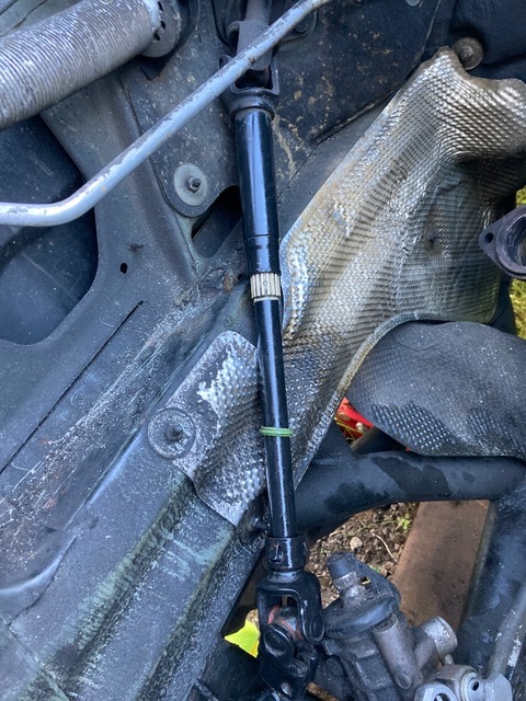
Using a female E11 torx bit, loosen & remove the steering column UJ from the rack pinion top & tie it up out the way (eg string from top of engine bay).
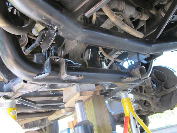
Remove the aluminium heat shields from around the Anti Roll Bar mountings (mixture of M8 screws & M10 nuts). Extraction might require some minor bending of the shields.
Using a 16mm bent ring spanner, loosen & remove the engine mounting bolts (2 bolts each side retaining engine mtgs to the subframe).
NB : RHS mtg is further forward on the subframe than the LHS. RHS is difficult / slow due to poor access (1/12th of a turn at a time !). RHS front bolt is slightly easier to remove if the intercooler hose is disconnected from the intercooler. BEWARE : Oil may come out of the intercooler / pipe. If it does, you may need to consider the condition of your turbos !
LHS is quite a bit easier, but still very difficult to start loosening the rear bolt.
The degree of bend in the spanner is critical to getting access !
Loosen & remove the 10mm nut holding the PAS pipe rubber vibration mounting to the front cross member (21mm open jaw spanner required on the metal flats next to the subframe ). Push the threaded portion through the subframe to allow the hose to move freely for next steps.
Unclip the engine mounting vacuum pipes from the various retaining clips. Check for / unclip any other retaining clips for the flexible PAS hoses.
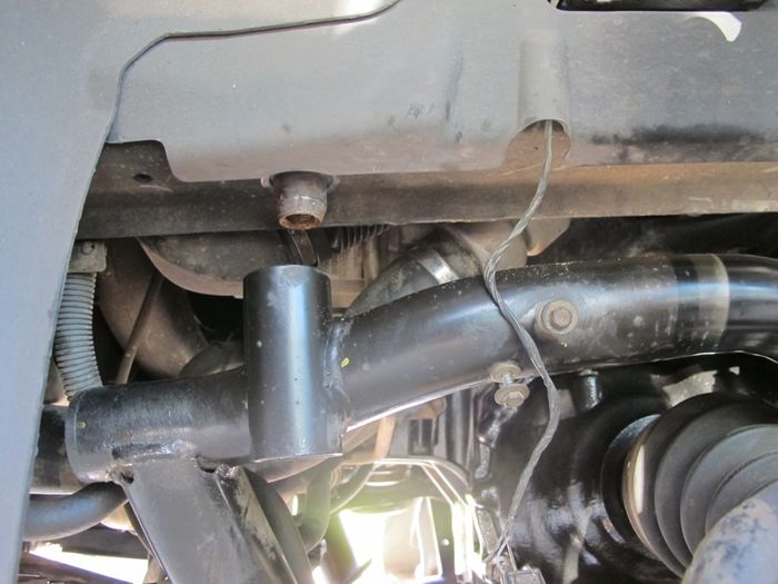
Loosen the 22 mm banjo bolt holding the “lower” flexible fluid pipe to the top of the rack. Remove the hose / banjo bolt from the rack (don’t lose the Dowty sealing washers). Access is not easy !
BEWARE : PAS fluid will leak out & need catching with rags. NB This might be slightly easier if done after PARTIALLY lowering the engine subframe as detailed below.
Cover the end of the hose with a small plastic bag & hold in place with eg elastic band . Push the hose out of the way to allow access to the top 19 mm banjo fitting. Loosen the 19mm banjo (more fluid loss !) & remove the fitting while catching the Dowty washers. Again use a plastic bag to cover the end of the pipe assembly / protect from dirt.
Use a female E14 torx bit to loosen the steering rack retaining bolts (2 off). 19 mm open jaw spanner needed to hold the top nut (accessible from the front).
Use a jack to lift the engine very slightly (5 or 6mm [¼ inch] max) under the oil pan / sump. Use a piece of wood 5 or 6 inches square to spread the load to the pan & then fit a substantial “prop” under the load spreader to stop the engine moving down if the jack “creeps”.
BEWARE : Engine movement can cause the viscous fan blades to damage the radiator – UNLESS you decide to remove it first (not quick !).
Loosen the 6 off 21mm bolts retaining the engine crossmember to the body “rails” (Each side has 1 at rear & 1 inside each of the 2 vertical “tubes”. Loosen & remove the 2 off 19mm bolts holding the engine & front crossmembers together. Support the front of the engine crossmember with a jack. Remove each of the rear bolts one by one, grease the threads & refit by 2 full turns (should be about 12mm [1/2 inch) “slack”.
Remove the front 4 off 21mm bolts & the 2 off 19mm bolts, so that the subframe can be lowered at the front via the jack, but be located / pivot around the remaining 2 rear bolts.
Add something to protect the LH driveshaft CV gaiter from damage as the subframe is lowered (very thick cloth, rubber etc).
Lower the subframe slowly with the jack until the subframe is very close to the LH CV gaiter (the front mounting tube of the subframe will be approx. 70 ~ 75 mm [approx. 3 inches] away from the body “chassis rail”.
Use axle stands or similar to safely support the front sides of the subframe at this height while the rack is extracted. Rotate the rack pinion anticlockwise to reduce the exposed RHS of the rack to approx. 0.5 inch (helps make it easier to remove the rack assembly )
Lift the rack backwards & upwards to clear the top rack retaining brackets, while pushing the rack to the RHS. Move the rack forwards at the RHS to allow the rack “column” to twist horizontal backwards while clearing the RHS CV . Further manipulation should then extract the rack from the LHS “opening”.
BEWARE : Avoid damaging the engine mounting vacuum pipes.
You’ve now got the rack out !
Before fitting the replacement rack, consider whether you want to clean up / deal with any surface rusting of the subframe or other components.
Also remove the LHS intercooler hose from the intercooler to check for / remove any oil. Refit afterwards. Repeat for the RHS if not done earlier.
Clean up the bagged flexible PAS hose ends & check the condition of the Dowty sealing washers (2 off per banjo). Replace any suspect / damaged seals. (NB there’s a different size on each banjo bolt)
Before fitting the replacement rack, clean up the servotronic valve port & transfer the metal plate / cardboard you used to blank off the port on the original rack.
Manipulate the replacement rack into place in the subframe & loosely add the retaining bolts & nuts (installation seems much more difficult than removal !).
BEWARE : Avoid damage to engine mounting vacuum pipe.
Lift the subframe front approx. halfway towards the chassis rails (approx. 30mm clearance). Fit the PAS flexible hose banjos to the rack & tighten while there’s increased access space.
Finish lifting the subframe up into contact with the body chassis rails with the jack, checking for correct positioning / pinching of hoses & cables & the engine mountings & the large subframe mounting spigots that locate in the subframe tube frequently (suspension height sensors & servotronic valve). Loose fit / loosely tighten the subframe retaining bolts & then check that everything is in position.
Start each of the engine mounting retaining bolts in their threads & tighten when all in.
The remainder is a reverse of the removal process.
Fit the TREs to the drumsticks with lots of grease on the threads & the same number of turns as when removed before tightening the locknut. Rotate the rack pinion to centralise the rack (equal amounts of rack outside of the housing either side + the steering column pinion alignment marks aligned (approx. 58mm of the rack exposed each side).
Remember to replace the suspension height sensor cable & Servotronic valve cable retaining clips / cable ties to prevent the cables being chafed by movement of the height sensor arms.
Tighten all fasteners to the relevant torques, fill the PAS reservoir with new fluid & re-connect the battery.
NB : The steering rack boots / gaiter retaining clips can be re-used if you know how, otherwise replace with new.
Start the engine & let it idle for a few minutes for the PAS fluid to partially fill the system. Top up the fluid, then turn the steering wheel slowly to the left and right to bleed air out of the system. The fluid will become aerated, so allow it to settle before repeating & again top up the fluid reservoir as required.
Get the tracking checked / adjusted as necessary.
Drive car & enjoy reduced knocking noises ! Paul,
2001 Discovery 2 TD5, 211,000 miles & climbing
2006 FFRR TDV8 Vogue 151,000 miles & now sold
Member of Midland (Land) Rover Owners Club, www.mroc.co.uk
Last edited by Pawl on 1st Nov 2020 7:45pm. Edited 3 times in total
|